Central Venous Catheter Task Trainer Phantom with Purple Vessels

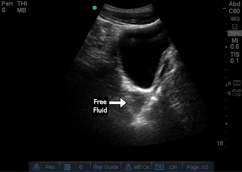
If you are using task trainer procedural phantoms for ultrasound guided vascular access you may notice a problem over time.  The phantom vessels may start to be filled with purple fluid.  If you have blue and red liquid to differentiate the artery versus vein in the phantom there are 2 reasons you could have purple fluid.

  1. Aspiration of fluid from one vessel and re-injection into the other, mixing the red and blue to form purple.
  2. There is a fistulous connection between the artery and the vein.

If the purple fluid is due to aspiration and injection of fluid from one vessel into the other that is easy to fix.  Drain and refill the vessels with red and blue.  Then instruct your users not to re-inject the fluid in to the phantom vessel.  Instead dispense of the aspirate into a container on the side with a separate one for each color.  This will prevent mixing and injection of air in to the vessels leading to artifacts.  This will also prevent the accidental injection of fluid in to the phantom tissue itself which can damage the inserts and reduce the life of the phantom.  You can then inject the fluid through the fill port later.

The other reason is if you have a fistula between the vessels.  The following video shows what an aterio-venous fistula can appear like on the phantom with both an electronic and hand pump model.

One way to fix both problems is to fill the vessels with a single color fluid so if there is mixing or a fistula it won’t matter.

Instructional video for the Accucath by Vascular Pathways (Bard)

Originally Published: 2015-Apr-29

Since this was originally published the Accucath has become a Bard product.

As a disclaimer I do not currently receive any funding or support from Vascular Pathways (or Bard). The devices are purchased by the healthcare institution where I practice.

The Accucath device is a peripheral intravenous catheter that has an integrates coil tip wire to allow a seldinger type insertion technique.  Think of your arterial catheters.

Theoretically this would allow you easier placement in smaller and more difficult vessels.  It is also supposed to help you navigate through valves and avoid small side branches (all of which I have had experience with and it can be frustrating).  This is a newer device and I have had good success with smaller vessels, however, we will see what happens as more difficult access cases occur.

Below is an instructional video on using the Accucath 2.25″ device for venous access.

I tend to capture an image of the wire in the vessel and the catheter in the vessel if I am able to based on the clinical situation.  I also tend to document that the wire was removed intact, at least currently since this is a newer device in my institution.

Primer Videos for Ultrasound

These 2 videos are meant to be primer videos for point of care ultrasound. These were designed to be used as part of a procedural education course.  The physics and knobology presentations are meant as an introduction and not as exhaustive or comprehensive reviews.  Think of them as for people who are starting to learn procedural ultrasound, off service residents who need an introduction, or even medical students rotating in EM.

Enjoy and feel free to use as you see fit, no point recreating the wheel.

Kyoto Kagaku US Guided PICC Phantom: Hands On

I got the chance to use and evaluate the Kyoto Kagaku Ultrasound guided Peripherally Inserted Central Catheter procedure phantom.  The phantom consists of a torso and an arm that articulates at the shoulder to be able to place the arm in different positions.

The upper arm has a replaceable area that can be ultrasounded and cannulated.  The targets are the cephalic and basilic veins.  The vessels outside of the insert are clear so you can see the wire and/or catheter threading. There is the ability to place the wire in to the SVC and the IJ.  There is a vessel that is used to fill the model and could be considered an azygos vein, but its take off is a little odd.

The video goes over the phantom’s parts and images along with demonstration of access and wire threading.

Disclosure: Phantom model was provided by Kyoto Kagaku for evaluation.

Central Line Kit Walkthrough and Line Placement

Originally Published: 2013-Jul-02

This video is a walk through of placing an ultrasound guided internal jugular central line in  a sterile fashion.  The technique and individual steps will depend on the brand of kit and how it has been customized for your institution.

This video was originally created as a review for the residents at my institution.  It focuses on the process of placing the line and less so on the ultrasound guidance.

Point of Care Ultrasound for Hernias

Originally Published: 2012-Feb-21

**This post was originally part of the ACEP Emergency Ultrasound Section’s Newletter in the Tips and Tricks section . The newsletter is located on the member only section of the site so I am posting here to make it more available.**

Patients commonly present with complaints of abdominal hernias and are frequent incidental findings in the emergency department. Incarcerated hernias can cause swelling, pain, and may require emergent surgical consultation if strangulated.

While an incarcerated hernia can be found on physical exam, ultrasound can assist in the management of these cases. Imaging the incarcerated hernia to identify the contents of hernia sac can help differentiate bowel from adipose tissue. As well, one can identify concomitant pathology such as free fluid, bowel wall thickening, pneumotosis coli, aperistalsis, and abnormal blood flow.

Diagnostic imaging is commonly described in many texts and articles; however, an additional step in the imaging protocol can help with the management of incarcerated hernias. Scan through the hernia sac and pay special attention to the abdominal wall for the break in the wall or the neck of hernia sac, this will allow planning for reduction. Identification of the neck allows the operator to direct the hernia contents toward the neck during manual reduction. It also allows the clinician to identify the size of the neck compared to the hernia contents.

Figure 1 shows an incarcerated ventral hernia containing small bowel. The neck can be identified by the defect in the abdominal wall. This hernia was successfully reduced by applying pressure from the lateral edge of the bowel loop toward the neck. Figure 2 shows the hernia post reduction containing only fat; the fascial defect is still visible.

While this large hernia had a midline neck, that is not always the case as demonstrated in Figure 3. The neck is visible and the hernia sac is laterally located. Evaluation of the hernia contents and neck location can aid in planning the reduction. Practice visualizing known hernias and the fascial defect or neck on patients with hernias that are not incarcerated or strangulated.

Figure 1: Incarcerated hernia with bowel and neck visualized

Figure 1: Incarcerated hernia with bowel and neck visualized

Figure 2: Post reductions fat containing hernia and neck are visualized

Figure 2: Post reductions fat containing hernia and neck are visualized

Figure 3: Small hernia lateral to the neck

Figure 3: Small hernia lateral to the neck

Tips and Tricks for the Pelvic Views during the FAST Exam

Originally published: 2011-Apr-18

This is a short article that my colleagues and I wrote for the American College of Emergency Medicine Emergency Medicine Ultrasound Section April Newsletter.

The full newsletter can be found here.

The Focused Assessment with Sonography in Trauma or FAST exam is one of the most common Point of Care Ultrasound exams performed in the Emergency Department.  As discussed in numerous forums, the FAST (or E-FAST) exam can be used in multiple clinical scenarios beyond the traumatically injured patient.  We will discuss two common errors that can lead to the misdiagnosis of subtle findings.

The pelvic windows in the FAST exam are often scanned hastily if the RUQ and LUQ do not show free fluid; however, subtle pathology can be missed if the windows are not surveyed in a thorough manner.

The urine-filled bladder results in posterior acoustic enhancement, which can obscure pelvic structures and pathology posterior to the bladder.  This will be amplified if the far field gain is not appropriately adjusted.  Structures may appear significantly more hyperechoic, and free fluid can be missed due to wash-out from an overgained far field image.  Figure 1 is an example of missed pelvic free fluid due to posterior acoustic enhancement.  The overgained far field obscures the free fluid.

Sagittal view of the bladder with free fluid.  The posterior acoustic enhancement leads to an overgained far field despite the appropriate gain settings of the near field.  This small amount of free fluid, caused by a liver injury, was mis…

Sagittal view of the bladder with free fluid.  The posterior acoustic enhancement leads to an overgained far field despite the appropriate gain settings of the near field.  This small amount of free fluid, caused by a liver injury, was missed on initial evaluation.

Figure 2 demonstrates a similar transverse view of the bladder, but with improved far field gain.  Internal echoes are visible within the free fluid due to posterior acoustic enhancement; however, further reduction in far field gain may reduce visualization of anatomic structures.  Sonographers must strike a balance between adjusting the far field gain to adequately visualize free fluid while still identifying posterior structures and boundaries.  This highlights the need to remain vigilant in looking for small amounts of free fluid or other subtle findings.  Despite the reduced far field gain and improved image, the persistent artifact within the fluid could mask this pathology.  Appropriate imaging and assessment in the suprapubic window requires an understanding of both the pitfalls of posterior acoustic enhancement, as well as any limitations that can be encountered when correcting for this artifact.

Sagittal view of the bladder with subtle free fluid.  Although the far field gain is better than Figure 1, there are still echoes within the free fluid due to posterior acoustic enhancement.  This highlights the need to be vigilant for sub…

Sagittal view of the bladder with subtle free fluid.  Although the far field gain is better than Figure 1, there are still echoes within the free fluid due to posterior acoustic enhancement.  This highlights the need to be vigilant for subtle findings in the FAST exam.

The second common error occurs while imaging the bladder in the transverse plane.   Sonographers commonly fail to adequately visualize the lateral edges of the structure.  One of the goals of transverse imaging is to evaluate for free fluid that is lateral to the bladder and may not be apparent on sagittal imaging.  Figure 3 demonstrates this potential pitfall.

Transverse view of the bladder with free fluid located laterally to the bladder.

Transverse view of the bladder with free fluid located laterally to the bladder.

Figure 4 shows a transverse view in which the lateral edges are not visualized.  This occurs most commonly either when the bladder is distended or when a small footprint transducer, such as the phased array or small curved array, is used.  If this occurs, the lateral edges need to be evaluated by scanning each half of the bladder separately on transverse imaging.

Transverse image of the bladder using a phased array transducer.  Due to the small footprint, the lateral edges of the bladder are not visualized and free fluid may not be visualized.

Transverse image of the bladder using a phased array transducer.  Due to the small footprint, the lateral edges of the bladder are not visualized and free fluid may not be visualized.